
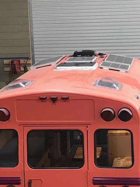
Wiring a bus is the part of the build that scares people the most, and honestly, I get it. But after spending a ton of time digging into this and talking to builders, I can tell you it’s not nearly as complicated as it looks once you break it into steps.
Wiring a school bus conversion comes down to understanding two separate electrical systems (12V DC and 120V AC), choosing the right wire gauge for each circuit, running wire safely through the bus, setting up a breaker panel for distribution, and connecting to shore power for campground hookups. The biggest safety concerns are undersized wire, missing fuses, and loose connections — those three things cause almost every electrical fire in a bus build. Get the wire gauge right, fuse every circuit, and use proper crimped connections, and you can wire a bus yourself even with zero prior experience.
Planning Your Electrical System (12V vs 120V vs Both)
When I first started researching bus wiring, I kept running into the terms 12V and 120V and it took me a while to really get what the distinction meant for my build. So let me save you some time.

12V DC is what your batteries store. Same type of power that runs your car’s headlights. In a bus, 12V powers LED lights, vent fans, USB charging ports, your water pump, and your fridge (if it’s a 12V model). These circuits run directly off your battery bank without needing an inverter, which makes them more efficient.
120V AC is what comes out of the outlets in a regular house. Your microwave, laptop charger, air fryer, coffee maker, mini-split AC — all 120V. To get that in a bus, you need an inverter that converts 12V DC from your batteries into 120V AC. Or you plug into shore power at a campground, which gives you 120V directly.
Do you need both? Almost certainly yes. I looked at a lot of builds trying to find someone who went all-12V or all-120V and it doesn’t work cleanly either way. Your water pump is 12V. Your Instant Pot is 120V. You need both running in parallel, and the good news is they share the same battery bank. Solar panels and alternator charger feed 12V into the batteries, some goes directly to DC circuits, the rest gets converted to 120V through the inverter. Two systems, one power source.
Understanding Your Power Needs
This is the step people want to skip, and I get the impulse because it feels like homework. But if you wire a bus without knowing how much power you actually use, you’re guessing at wire sizes, breaker ratings, and battery capacity — and guessing is how stuff goes wrong.
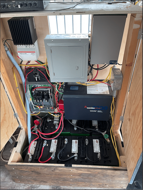
I covered the full sizing math in the solar sizing article, so I won’t repeat all of it here. But the short version is this: list every electrical thing you plan to run, find its wattage, estimate daily hours of use, and multiply to get watt-hours per day.
A quick reality check on some common items:
- LED lights, maybe 50 watts total across the bus
- 12V compressor fridge, around 50 watts average (runs in cycles)
- Laptop charger, 60 watts
- Phone charger, 15 watts
- Water pump, 60 watts but only runs a few minutes at a time
- Vent fan, 30 watts
- Microwave or air fryer, 1,000-1,700 watts but only for short bursts
That last category is what trips people up. A microwave doesn’t use much total energy because you only run it for 5 minutes. But while it’s running, it draws a massive amount of current, and your wiring between the inverter and the outlet needs to handle that peak load without overheating. This is why understanding your power needs matters for wiring specifically, not just for battery sizing.
Someone asked me once, “How do you have electricity and water etc?” and the honest answer is that it’s all self-contained. Solar panels charge batteries, batteries run everything electrical, and the whole system lives inside the bus. There’s no hookup you need, no monthly bill, no external dependency unless you choose to plug into shore power. The water side is a separate system entirely — we’ve got a whole article on that.
Wire Gauge and Why It Matters
Alright, this is the section that could save your bus from catching fire. I’m not being dramatic. I was reading through a skoolie forum last year and this guy posted photos of a wire that had melted through its insulation behind his wall paneling. He smelled burning plastic and found it just in time. The cause was 14-gauge wire on a circuit that needed 10-gauge. That’s it. Wrong wire size, and he almost lost the whole bus.

Wire gauge is a number that indicates thickness, and here’s the part that confuses people at first — the lower the number, the thicker the wire. So 4-gauge wire is much thicker than 14-gauge. Thicker wire carries more current without heating up.
How do you know what gauge to use? Three things determine it: the current (amps) the circuit carries, the length of the wire run measured round-trip, and your acceptable voltage drop which you want under 3% for 12V systems. At 12 volts you don’t have much margin — a 5% drop means you’re losing over half a volt, and that matters.
Don’t try to memorize a chart. Use a wire gauge calculator online. You punch in your amps, wire length, and voltage, and it tells you what gauge to use. I found myself using one constantly when planning out my circuits because every run is different.
Between battery bank and inverter, you’re looking at 2/0 or 4/0 gauge — thickest wire in your system because the inverter can pull 200+ amps at peak load. Keep this run under 3 feet if you can. Between solar panels and charge controller, usually 10 or 8 gauge. For individual 12V circuits like lights and fans, 14 or 12 gauge is usually fine.
And one thing I learned that I wish I’d known earlier — always use marine-grade tinned copper wire for your DC circuits. Regular copper corrodes over time, especially if you’re in humid climates or near the coast. Marine grade has a tin coating that prevents that. Costs maybe 20% more and it’s the kind of thing you don’t think about until your connections start getting flaky three years in.
Running Wire Through the Bus
Every bus is different so the exact wire routes depend on your layout. But there are principles that apply to pretty much every build.
Run your wires before you close up the walls and ceiling. I talked to a builder at a meetup who sheeted his entire ceiling in tongue-and-groove pine and then realized he hadn’t run a single wire up there for the lights. Had to pull down about a third of it, run the wires, and put it all back. Said it cost him a full weekend he’ll never get back. Wiring comes after insulation and framing but before any finish work.
Use the existing channels in the bus frame whenever you can. School buses have steel ribs running along the walls and ceiling, and the cavities between those ribs are natural wire channels. Some builders run wire through the old conduit the school bus’s original wiring used. It’s already there, might as well use it.
Protect your wires with split loom tubing or conduit. A bare wire rubbing against a metal edge will eventually wear through its insulation and short out. At any point where wire passes through a hole in metal, use a rubber grommet. No exceptions.
Keep AC and DC wires separated — opposite sides of the bus, or at least 6 inches apart. This prevents interference and it’s a code thing.
Label everything. Both ends of every wire. When the wires are exposed during the build it all makes sense. Six months later when you’re troubleshooting a dead outlet from behind a panel, you’re going to wish you had labels.
The Breaker Panel and Distribution
All your circuits need to connect somewhere central, and that’s your breaker panel. Most buses actually need two — one for 12V DC and one for 120V AC.

For 12V, you’ll use a fuse block rather than a traditional breaker panel. Something like a Blue Sea Systems 12-circuit fuse block. Each circuit gets its own fuse sized for the wire gauge. Lights on one, fan on another, water pump on another. If something goes wrong on one circuit, that fuse blows and everything else keeps running.
For 120V, a small residential-style breaker panel, usually 4-8 circuits. Kitchen outlet where you plug in the microwave should be on its own 20-amp circuit. General outlets can share a 15-amp circuit.
Mount these somewhere accessible but out of the way — a closet, under a bench seat, a dedicated utility area near the batteries. Don’t bury them behind something you’d have to demolish to reach.
Between the battery bank and everything else, you want a main disconnect switch that kills all power in one turn. If something goes wrong, you need to cut power instantly. These cost about $20 and they’re one of the most important safety components in the system.
Someone brought up a good point — “What about battery fumes? Would it be better with a compartment outside?” If you’re running AGM batteries, off-gassing is minimal and you can mount them inside in a vented battery box. Flooded lead-acid batteries produce hydrogen gas while charging and absolutely need ventilation, but I don’t recommend them for a bus build anyway. Lithium LiFePO4 batteries don’t produce fumes at all, which is another reason they’ve become the standard. Worried about fumes? Go lithium.
Connecting to Shore Power
Even if you plan to be off-grid most of the time, install a shore power hookup. It costs very little during the build and saves headaches later. RV parks, campgrounds, a friend’s driveway — shore power lets you run on grid electricity while charging your batteries.
You need a 30-amp shore power inlet (NEMA TT-30) on the outside of the bus. Standard plug that matches any RV park. Drill a hole, mount the inlet box, seal it with butyl tape and caulk, run the wire inside.
From the inlet, the power goes to a transfer switch. This is the part people skip, and it’s dangerous. A transfer switch makes sure only one power source feeds your AC panel at a time — either the inverter or shore power, never both. Without one, you risk backfeeding power from your inverter out through the shore power inlet, which could electrocute someone plugging or unplugging the cable. I’ve heard of it happening.
Manual transfer switches run $50-100, automatic ones $150-300. Some inverter/charger combos like the Victron MultiPlus have transfer switching built in. From the transfer switch, power goes to your AC breaker panel same as it does from the inverter.
One more thing — get a surge protector for your shore power connection. Campground pedestals are notoriously unreliable. Low voltage, reversed polarity, all kinds of problems that can fry your electronics. A Progressive Industries surge protector runs $100-300 and it’s cheap insurance.
Common Wiring Mistakes to Avoid
I’ve been collecting these from forum posts, build videos, and conversations with builders, and it’s kind of amazing how the same mistakes come up again and again. So let me just run through the ones that I see most often, because some of them are easy to avoid if you know about them ahead of time.

Undersized wire between batteries and inverter. Number one fire risk. Your inverter can pull 200+ amps at peak load. If the wire can’t handle that current, it heats up, melts insulation, shorts out, catches fire. Use the calculator, size up if you’re on the borderline, keep the run short.
No fuse between battery and inverter. Your inverter’s built-in fuse protects the inverter, not the wire leading to it. You need an ANL fuse or Class T fuse on the positive cable as close to the battery as possible. It’s a $5 holder and a $3 fuse. Please just install it.
Using wire nuts. Wire nuts are for houses. Houses don’t bounce down the highway at 55 mph. Vibration loosens them over time and loose connections arc and start fires. Use ring terminals, butt connectors, or crimp lugs with heat shrink. And use a proper crimping tool, not pliers — a good one costs $30.
Forgetting inverter draw on the DC side. This one bit me when I was planning my system. Your microwave draws 1,200 watts from the 120V outlet, but the inverter is pulling that from 12V batteries, which means the DC side is carrying about 100 amps. At 12 volts, current is TEN TIMES higher than at 120 volts for the same wattage. People wire their AC side perfectly and then use laughably thin wire on the DC side. The battery-to-inverter connection carries the most current in your system. Size it accordingly.
Not labeling circuits. Future you is going to be lying on the floor with a headlamp, reaching behind a panel, trying to figure out which wire goes to the bathroom light. Label everything. Both ends.
Not leaving room to expand. You start with 200Ah of batteries and four circuits. A year later you want to add capacity, run a new outlet, add a vent fan. If your battery compartment is packed tight and your fuse block is full, adding anything means reworking the whole setup. Leave extra fuse slots. Leave room in the battery box. Run a couple spare wires during the build. Fifty feet of wire costs $20 now. Tearing out wall panels to run it later costs a weekend.
So after digging into all of this, here’s what I’d tell someone starting out. Don’t try to learn the whole electrical system at once. Learn it in chunks, in the order you’ll build it — power needs first, then 12V distribution, then the 120V side, then shore power. Each piece builds on the one before it.
I went into this knowing basically nothing about electrical systems and I’m telling you, if I can wrap my head around it, you can too. The non-negotiable thing is safety — fuse everything, size your wire right, make proper connections. Get those three things right and the rest is just connecting A to B. For the full picture on solar panels, batteries, inverters, and sizing, check out the complete electrical and solar guide. That covers component selection while this article covers wiring, and together they’re pretty much everything you need.